PosiTracker™|TL LTE
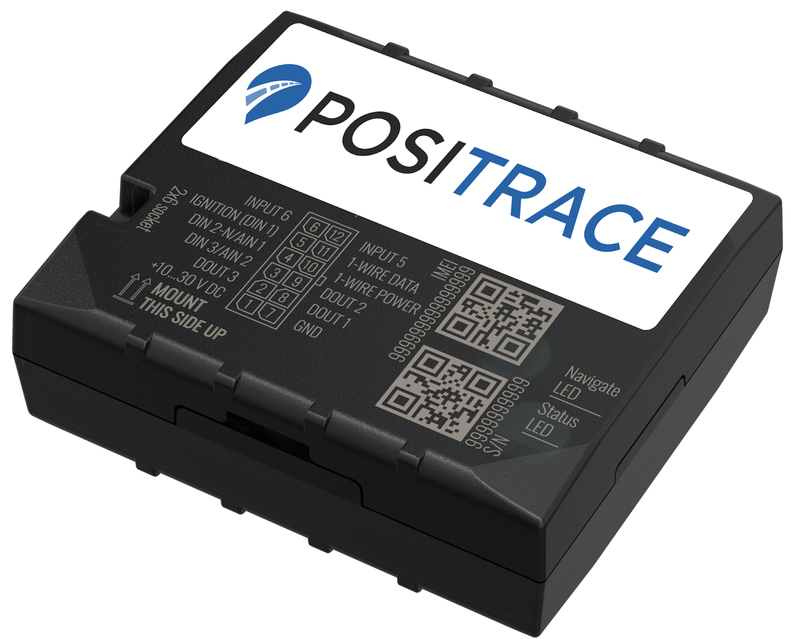
DriverID Based Immobilizer
Wiring color chart:

|
Pin |
Label |
Cable Color |
Function |
|
Pin 1 |
+10…30VDC |
Red |
Constant Power (+10-30V DC) |
|
Pin 2 |
DOUT3 |
Gray |
Output 3 (Max. 0.5A DC) |
|
Pin 3 |
DIN3 |
Solid White |
Panic button / Alarm (0-30 V DC / Power | PosiTrace input 2) ** |
|
Pin 4 |
DIN2 |
Green Stripe |
PTO* (+0-+30 V DC, option to be Ground Trigger | PosiTrace input 1) |
|
Pin 5 |
DIN1 |
Yellow |
Ignition |
|
Pin 6 |
INPUT 6 |
Blue Stripe |
Not in use (TX EXT) |
|
Pin 7 |
GND |
Black |
Constant ground, Driver ID Ground |
|
Pin 8 |
DOUT1 |
Orange Stripe |
Immobilizer* (digital output 0.5A DC) |
|
Pin 9 |
DOUT2 |
Solid Purple |
Digital output (Max. 0.5A DC) |
|
Pin 10 |
1WIRE PWR |
Solid Blue |
Temperature sensor |
|
Pin 11 |
1WIRE DATA |
Solid Green |
Temperature sensor, Driver ID Data |
|
Pin 12 |
INPUT 5 |
Yellow Stripe |
Not in use (RX EXT) |
DIN2-N – PosiTrace Input 1 in PosiTrace Locate (Default: PTO)
DIN3 – PosiTrace Input 2 (Default: Panic Button, can also be PTO)
* For ground trigger option on PTO input Green/White wire, please contact Support for updated configuration.
Driver ID:
|
PosiTracker TL LTE |
Driver ID |
|
Pin 7 (Black) ground |
Ground (black) |
|
Pin 11 (Green) data |
Data (grey) |
|
|
|


Buzzer Install (optional) Please ensure buzzer is set up in the PosiTrace Platform before installing
Buzzer is compatible up to 24V of power. Connecting to Pin 10 Blue will provide low voltage / lower volume. Connecting to Pin 1 Red provides 12V or 24V depending on vehicle and produces louder volume.
|
PosiTracker TL LTE |
Driver ID |
|
Pin 9 (Purple) Output 2 |
Ground (black) |
|
Pin 10 (Blue) PWR 3V |
PWR (red) Choose 1 pwr option |
|
Pin 1 (Red) PWR 12V |
|
|
|
 |

Tap behavior:
When tapping your key, please remember it is a tap and not a swipe. Firmly attach the Driver ID fob to the reader in full and leave for 2 to 3 seconds to ensure reading is completed.
If you have installed the buzzer, a short beep will occur when there has been a successful read of the Driver Key, after which it is safe to remove the key.
If your buzzer makes a long beep (5 seconds) – your wiring is correct (physical install is now finished), but you must complete the buzzer setup below on the PosiTrace Platform.
Buzzer Setup:
The Buzzer should be assigned to output 2 in the PosiTrace Locate platform which will reduce the sound from 5 seconds (long beep) to 200 milliseconds (short beep). Please make sure each of your devices has an Equipment Name before proceeding.
- Account > Equipment List
- Use the magnifying glass (View Details) icon, or click on the Equipment name.
- Select the Inputs / Outputs tab, and add your Buzzer into Output 2

If your Driver ID kit has an LED light, please use the following guide.
Immobilizer Wiring

 |
Relay Type 1 |
Relay Type 2 |
Function |
|
Pin 85 |
Pin 85 |
PosiTracker Device |
|
|
Pin 86 |
Pin 86 |
Triggered positive voltage (+12V) |
|
|
Pin 30 |
Pin 30 |
Starter wire; engine |
|
|
Pin 87a |
Pin 87a |
Starter wire; ignition (switch) |
|
|
Pin 87 |
Pin 87 |
not in use - opposite from 87a |
DriverID Controlled Immobilizer:
It is possible to control a vehicle’s ability to start via Driver ID. For this option, you must have a Driver ID system installed, an immobilizer relay installed, and the correct service plan features on your subscription.
Please note you will no longer have manual control over an immobilizer relay through the PosiTrace platform with this option.
Vehicles must be turn-key ignition, combustion-engine cars and trucks
Operation is as follows:
- Ignition state: Turn your key to the ON position where all your dashboard lights are lit up.
- Tap key: firmly tap your Driver ID fob key to the Driver ID reader for at least 3 seconds. A signal is sent to disable your immobilizer relay on DOUT (Pin 8, Orange/White wire).
- Turn key to Start position to start your vehicle.
If your vehicle does not start, please try tapping the key again; In rare occasions, it may not communicate the status to the reader and a second attempt can be made.
Remember to firmly attach the key in such a way that the flat surface of the fob makes complete contact with your reader, and that the tap is not less than 3 seconds in length to ensure a reading.
LED reference:
|
Status LED |
Description |
|
Blinks: 1x every 1 second |
Normal operation |
|
Blinks: 1x every 2 seconds |
Sleep Mode |
|
Blinks quickly for a short time |
Modem Activity |
|
OFF |
Not working, not powered, |
|
Navigation LED |
Description |
|
Steady: ON |
No GPS signal |
|
Blinks: 1x every 1 second |
Normal operation |
|
OFF |
Sleep mode OR |
|
Blinking Fast Constantly |
Device firmware is being updated |