PosiTracker™|QV LTEi
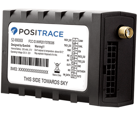
Installation Guide
Installation Checklist:
- A clear understanding of wiring diagram and installation procedure
- Recommended: Qualified installer skilled in vehicle electrical systems
- Correct gauge and length of any additional wiring
- Verify polarity, battery voltage (8-32 Volts DC) & ground with voltmeter
- Mounting location free from GPS-obscuring material, extreme heat, moisture and excess dirt, or excessive vibration.
- If relying on the internal antenna, Install label facing UP.
- Install all wiring connections securely with some slack in wires
- Follow enclosed wiring diagrams and color code chart
Before Installation begins:
- Write down the IMEI number of your device..
- Write down vehicle identification such as License Plate or VIN.
- Recommended: photograph the installation location of the device.
- Find appropriate mounting location for your device, or its antenna.
- Not covered by any metal.
- Clean, dry, and in an area free from excessive vibration
- Recommended install location: just under plastic dash cover
- Secure mounting after wiring is completed and tested.
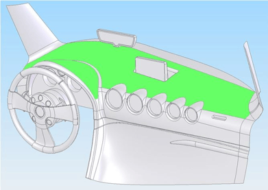
Recommended Installation Location for Passenger Car
Installation Instruction:
- Pin 11 (red) - Constant power, 10 to 30 V DC
- Recommended: positive contact on vehicle battery. Other acceptable locations include the power cable inside the fuse box, or the power supply where the vehicle’s computer fuses reside.
- Please do not connect constant power to an accessory as it may lose power when the ignition is off. If you have a Kill Switch, please connect to power at a point where the switch will not kill the GPS unit, leaving the vehicle without tracking for towing situations.
- Pin 6 (black) - Uninterrupted Ground source
- GND must be connected to a designated ground point or wire. Connecting the GND at an arbitrary point on the mass of the vehicle may result in unstable device operation or failure.
- Pin 3 (white) - Ignition (switched power, (5-32V DC)
- Connect to true ignition, positive voltage must be provided only when ignition is running. The third (ON/RUN) position of the key is recommended.
- Please avoid connecting to accessories, as this may cause false trips, incorrect idling, or power disconnection behavior.
- If an ignition source is not easily found, you may leave the white ignition wire completely disconnected. Please contact Support with your IMEI # and let us know to enable Virtual Ignition (may be less accurate than hardwired ignition)
- Optional
- Pin 13 (Orange), Pin 12 (Blue), and Pin 14 (Yellow) are used for PTO equipment, panic button and immobilizer. Requires triggered ground source. Additional installation guides and features may be required.
- Pin 9 (Grey/Black), Pin 10 (Grey/White), Pin 6 (Black), Pin 11 (Red) are used for Fuel Sensor connection. An additional installation guide and a qualified fuel-sensor installation technician is required.
- Pin 16 (Green) is used for 1WIRE devices such as temperature sensors and Driver ID readers. Both are grounded to Pin 6 (Black). A separate manual for these add-ons is available.
- For OBDII, J1708 and J1939 installation instructions please refer to the additional installation guides.
- Optional external GPS-only antenna (available on request for challenging install locations)
- For Seat Belt Unbuckled detection, please connect to one of the indicated PTO wires and ensure you have requested the PTO feature from your account manager.
Switch on the backup battery:
To use the backup battery, the switch must be in the ON position. The switch on the case and the ON/OFF position are shown below.
Please note: USB interface is only for programming by PosiTrace Support.
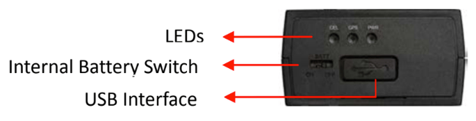
LED reference:
|
LED |
LED Status |
Device Status |
|
PWR - RED |
ON |
Device powered. Backup battery is fully charged. |
|
OFF |
No power provided. Internal battery voltage is lower than 3.35V |
|
|
Fast flashing |
Device powered. Backup battery charging. |
|
|
Slow flashing |
No external power. Working on battery. Battery voltage is below 3.65V |
|
|
GPS - BLUE |
ON |
Good GPS reception |
|
Fast flashing |
Searching GPS info |
|
|
Slow flashing |
No GPS data or GPS error |
|
|
CELL - GREEN |
ON |
SIM card needs pin code to unlock |
|
Slow flashing |
Registered on cell provider |
|
|
Fast flashing |
Searching cell info |
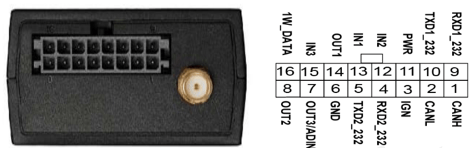
Wiring color code chart:
|
Pin |
Cable |
Function |
|
Pin 1 |
Brown/White |
CAN-H |
|
Pin 2 |
Brown/Black |
CAN-L |
|
Pin 3 |
White |
Ignition (triggered positive voltage input 8-32V DC) |
|
Pin 4 |
Orange/White |
Additional Serial port, RXD |
|
Pin 5 |
Orange/Black |
Additional Serial port, TXD |
|
Pin 6 |
Black |
Constant ground |
|
Pin 7 |
Brown (Solid) |
Output 3 (open drain (ground)) |
|
Pin 8 |
Grey (Solid) |
Output 2 (open drain (ground), Driver ID Buzzer) |
|
Pin 9 |
Grey/Black |
Red wire of DUT-E fuel sensor (see additional guide) |
|
Pin 10 |
Grey/White |
White wire of DUT-E fuel sensor(see additional guide) |
|
Pin 11 |
Red |
Power (constant positive voltage 8-32VDC) |
|
Pin 12 |
Blue |
PTO 2 (triggered ground input) |
|
Pin 13 |
Orange (Solid) |
PTO 1 / Panic button (triggered ground input) |
|
Pin 14 |
Yellow |
Immobilizer / Output 1 (triggered ground output, relay is required) |
|
Pin 15 |
Pink |
PTO 3 (triggered ground input) |
|
Pin 16 |
Green |
1WIRE data (temperature sensor, Driver ID) |
Panic Button installation (Optional)
- Pin 13 (Orange) is normally used for panic button installation; however, any ground-trigger input can be used. You must remember which input (1, 2, or 3) was connected to set up your Panic Alarm in the Locate platform.
- The Panic Button has 2 wires: connect one to the Input (eg: Orange Pin 13) and the other to your Ground connection.
It may take up to 30 minutes for the device to recognize the panic button after Locate Setup is completed.
Locate Setup for Panic Button or PTO Ensure you have named your vehicle (Account > Equipment list). View your equipment with the magnifying glass. Go to the Inputs / Outputs tab and find the Input number that matches your installation wiring.
 If you are setting up an Alarm, and it is already set to PTO, you must delete PTO from this option first:
 Then, add in your Alarm or PTO option and click Save.

Temperature Sensor Installation (Optional)
- It is possible to connect up to 4 temperature sensors to one GPS Device using up to 100’ cable (18-22 AWG, 2- or 3-wire, shielded).
When mounting temperature sensors always try to find a place closer to the ceiling of a trailer/refrigerator where they will not be damaged by commodities being loaded. - Please refer to the diagram below for connecting temperature sensor cable to PosiTracker|QV LTE wire harness based on your hardware.
In the case of a 3-wire sensor, please note that both the Red and Yellow cables will be wired together to ground, and the sensor will receive appropriate power levels through the Data wire.
|
PosiTracker |
Temperature Sensor |
Temperature Sensor |
|
Pin 6 (Black) |
Ground (red) |
Power |
|
Ground |
||
|
Pin 16 (Green) |
Data (white) |
Data (white) |
 |
 |
 |
Immobilizer
An immobilizer is an automotive relay as a switch, to prevent a system in the vehicle from starting, such as the Vehicle Starter, effectively immobilizing the vehicle. This switch is controlled remotely through the PosiTrace platform using the Immobilizer Arm / Disarm options.
 |
Relay Type 1 |
Relay Type 2 |
Function |
|
Pin 85 |
Pin 85 |
PosiTracker Device |
|
|
Pin 86 |
Pin 86 |
Triggered positive voltage (+12V) |
|
|
Pin 30 |
Pin 30 |
Starter wire; engine |
|
|
Pin 87a |
Pin 87a |
Starter wire; ignition (switch) |
|
|
Pin 87 |
Pin 87 |
not in use - opposite from 87a |

If GPS ignition is wired to the same starter/ignition wire that will be cut by the relay, the relay must be installed AFTER the device’s ignition wire connection.
For “Triggered positive voltage”, it is better to use a wire that will provide voltage when the key is in the “Run” / “Crank” position to prevent excessive battery drain. Constant positive power from battery (+) can be used, but the battery will drain more quickly.
User accepts all risk associated with having an ability to immobilizer a vehicle remotely and is solely responsible for any incorrect or untimely use that may lead to risk, loss, liability, damage, or costs, including but not limited to bodily injury or property damage.