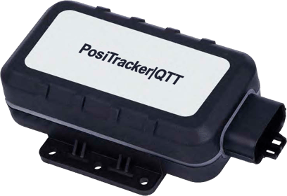
PosiTracker | QTT
Version 1 and 2
Installation Guide
Installation Instruction:
- Before installing the device into a vehicle:
- Write down IMEI number of the device from barcode
- Write down vehicle license plate/VIN or identification number
- Take pictures of device installation for future references.
- PosiTracker|QTT mounting location
- This device has a built-in antenna: Please make sure the installation location is not covered by any metal parts.
- Identify a solid mounting location away from extreme heat/vibration.
- The device can be installed vertically or horizontally. The label should either face away from the trailer (vertical) or UP toward the sky (horizontal).
|
Warning: Water should not be permitted to trickle into or toward the connection socket, as this may lead to permanent water damage over time. |
- For vertical installation, the cable must be located below the device.

- For horizontal installation, the cable must be facing away from the direction of common travel to prevent driving water/wind exposure to the connector side.
|
It is possible to install device underneath a trailer or rail, however this will negatively impact GPS reception. Make every effort to face label-side of device toward open air. |
- Your device is weather-resistant but should not be submerged or placed in standing / pooled water.
- Please do not paint or coat your device with any material. Doing so may compromise the weather-resistant features.
3. Wiring:
|
Basic 3-Wire Install |
|
|
2-Wire Install
|
|
|
Optional Secondary Power Wiring: Your device can connect to a second power source using Pin 2 (red/green - power) and Pin 4 (black - ground) wires. |
|
 Please contact Support to enable Virtual Ignition configuration
4. Optional:
- Pin 11 (Blue), Pin 12 (Yellow), Pin 13 (Brown) and Pin 14 (Orange) are used for PTO equipment, panic button and immobilizer. Requires triggered ground source.
- Pin 9 (Gray), Pin 8 (Black/White) and Pin 7 (Red/White) are used for Temperature sensor installation.
- Enclosures are available for this device type to further protect it from the elements. Please contact your account manager to find out more.
Temperature Warnings:
Ideal operating temperatures for optimal performance are as follows:
- Regular hardwired operating temperature: -30 to +80 C
- Optimal Lithium battery charging temperatures: 10 to 45 C
- Extended operation below 10 C may prevent the battery from charging. In the event the battery is discharged over long periods of time, it may be unable to fully recover.
General Installation Diagram:

Installation on a trailer / flatbed:
There are two pairs of power/ground cables that are included in the 18-pin wire harness. Choose the first pair (pins 1 and 3, red and black wires) and connect to power and ground pins on the trailer connector, usually mid and top pins.

The second pair (pins 2 and 4, red/green and black wires) can be connected to ground and AUX/ABS pins of the trailer connector.
Wiring Pins Diagram:


Wiring color code chart:
|
Pin |
Cable |
Function |
|
1 |
Red |
Power (constant positive voltage 8-32VDC) |
|
2 |
Red/Green |
Secondary Optional Power (11-28VDC) |
|
3 |
Black |
Constant Ground |
|
4 |
Black |
Secondary Optional Ground |
|
5 |
White |
Ignition (triggered positive voltage input 5-32VDC) |
|
6 |
Green |
Not applicable |
|
7 |
Red/White |
Used for Temperature Sensors |
|
8 |
Black/White |
Used for Temperature Sensors |
|
9 |
Gray |
Used for Temperature Sensors |
|
10 |
No cable. |
|
|
11 |
Blue |
PTO1 (triggered ground signal) |
|
12 |
Yellow |
Panic button (triggered ground signal) |
|
13 |
Brown |
PTO2 (triggered ground signal) |
|
14 |
Orange |
Immobilizer (open drain output) |
|
15 |
Purple |
Not applicable |
|
16 |
Purple/White |
Not applicable |
|
17 |
Pink |
Not applicable |
|
18 |
White/Black |
Not applicable |
LED reference:

|
LED |
LED Status |
Device Status |
|
PWR - RED |
ON |
Device powered. Backup battery is fully charged. |
|
OFF |
No power provided. Internal battery voltage is below 3.46V |
|
|
Fast flashing |
Device powered. Backup battery charging. |
|
|
Slow flashing |
No external power. Working on battery. Battery voltage is below 3.6V |
|
|
GPS - BLUE |
ON |
Good GPS reception |
|
Fast flashing |
Searching GPS info |
|
|
Slow flashing |
GPS error |
|
|
GSM - GREEN |
ON |
SIM card needs pin code to unlock |
|
Slow flashing |
Registered on cell provider |
|
|
Fast flashing |
Searching cell info |
Slow flashing: approx. every 2 seconds
Fast flashing: approx. every 1 second
Temperature Sensor (Optional)
|
PosiTracker |
Temperature Sensor |
Temperature Sensor |
|
Pin 6 (Black) |
Ground (red) |
Power |
|
Ground |
||
|
Pin 16 (Green) |
Data (white) |
Data (white) |
 |
 |
 |
Contact us:
- Email: support@positrace.com
- Tel: 1-877-787-2231 x2
- Address: 250 - 5172 Kingsway, Burnaby BC Canada V5H 2E8