Installation steps:
1. Identify mounting location:
-
Identify solid, heat / vibration / moisture-free mounting location. Recommended location: between windshield and dashboard under top plastic cover.
- Ensure location is not covered by any metal parts
-
Label must face down
-
Secure mounting after wiring is completed and tested
2. Before installing device into vehicle:
-
Check that internal battery switch is turned ON (located inside the SIM card compartment)
-
Write down IMEI number (under barcode) of the device
- Write down license plate/VIN or any identification number of vehicle.
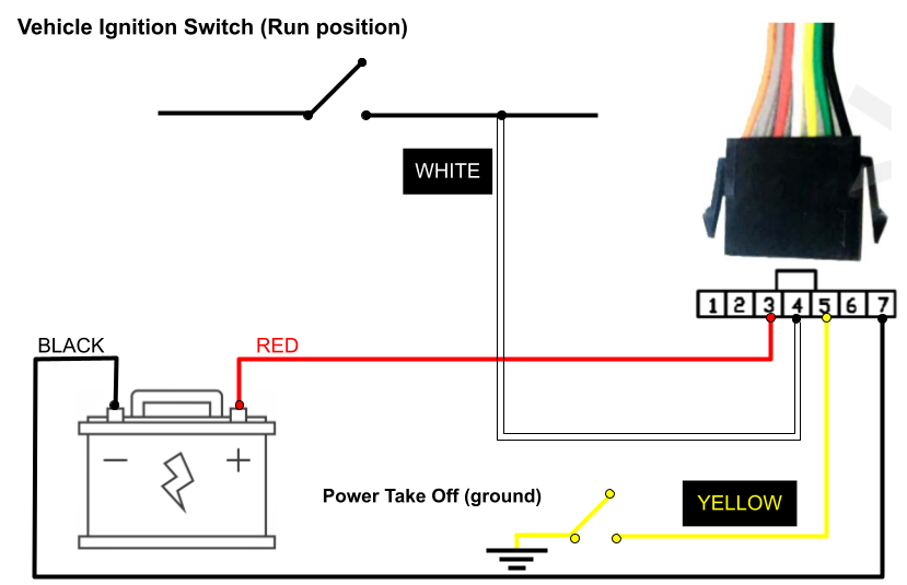
3. Basic installation (installation diagram available at the end):
A multimeter is recommended to verify polarity, battery voltage & ground. Make sure you have the correct gauge and length of any additional wiring needed. Ensure wiring connections are secure with some slack in the wires.
-
Pin 3 (red) - constant power from 8 to 32 Volts DC.
-
Pin 7 (black) - constant ground.
-
Pin 4 (white) - ignition detection. Positive voltage must be provided only when ignition is running, and zero volts when the ignition is off.
-
Recommended: 3rd (run) position on ignition switch, or fuse panel “ignition” source if available. Do not connect ignition to Accessories which may result in false trips.
-
Virtual ignition: if an ignition source is not easily found, you may leave the white ignition wire completely disconnected. Please contact Support with your IMEI # and we can enable Virtual Ignition, which will simulate ignition based on motion of the vehicle.
-
- Pin 5 (yellow) - PTO equipment (requires triggered ground source).
- Pin 6 (green) - Immobilizer installation
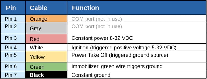
Wiring color code chart
Immobilizer (optional, requires additional feature):
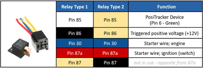
Note: for “Triggered positive voltage” source it is better to use a wire that will provide positive voltage when the key is in the “Run” and “Crank” positions to prevent excessive vehicle battery drain.
Installation diagram: