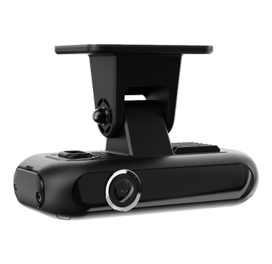


Camera Overview
Back of camera

|
Number |
Definition |
Feature |
|
1 |
Multi-function Button |
Wi-fi Switch, Panic Alarm |
|
2 |
LED Indicator |
Indicates device state |
|
3 |
Microphone |
Picks up Cabin audio |
|
4 |
Speaker |
Virtual Voice Alerts |
|
5 |
Bracket Base |
With adhesive pad to install on windshield |
|
6 |
Bracket Shaft |
Adjust camera angle |
Front of camera

|
Number |
Definition |
Feature |
|
1 |
Front Camera Lens |
Road-facing camera view |
|
2 |
Cable Outlet |
Connect wire harness |
|
3 |
Bracket Base |
With adhesive pad to install on windshield |
|
4 |
Bracket Shaft |
Adjust camera angle |
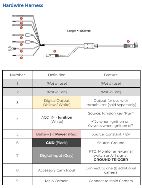
Hardwire Install
 Ignition: Positive voltage must be provided only when ignition is running, and zero volts when the ignition is off.
Recommended connection: 3rd (run) position on ignition switch, or fuse panel ignition source if available.
Never connect ignition to Accessories, or a power source connected to an
accessory, which may result in unstable ignition detection which will affect video recording.
 Power: Constant, uninterrupted power is required to operate the camera consistently. Stable +12V of power is required to prevent the camera from going offline.
Ground: designated ground point or wire. Connecting the GND at an arbitrary point on the mass of the vehicle may result in unstable device operation or failure.
|
To verify camera view, calibrate an AI dashcam, or retrieve videos directly from the camera, please install the Mobile App listed in the documentation below. |
Power Take-Off (Optional):
The power take-off feature allows you to connect the camera’s available Digital Input wire to an electrical source for monitoring of additional vehicle equipment. Some examples of this might include:
-
Winches or Lifts
-
Salt or Sand spreaders
-
Doors being open
-
Seat Belts that are unbuckled
This camera’s Input wire triggers on a Ground signal. If you have a positive- trigger system to monitor, please use an automotive relay to invert the electrical signal from positive to ground.
Plug-and-Play Install (Optional)
 You may have ordered an optional OBD cable for plug-and-play installation
In this case, you will no longer use the device’s default hardwire cable; however, please keep the hardwire cable, in addition to the OBD cable, in case you need it at a later date.
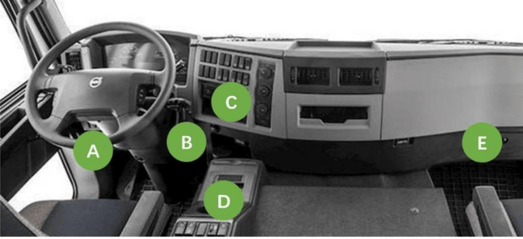
The OBD cable will be plugged in directly to the camera’s small 10-pin connector. Then, connect the OBD end of the cable to the relevant OBD diagnostic port in the vehicle.
Common locations of OBD ports are shown below, though frequently it will be underneath the steering column.
While using the OBD option, your ignition is simulated by the camera’s accelerometer. This results in ignition detection that may not be quite as accurate as hardwired ignition (may result in minor false ignition events related to vibration in or near the vehicle).
If tracking metrics such as Engine Hours, idling, and accurate ignition events is important for your business operations, please opt to hardwire your cameras for stability.
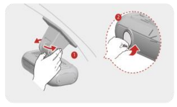
Mount Camera
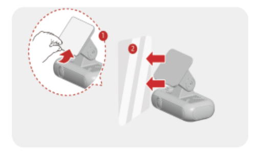
Remember to remove the Lens Cover and protective lens film.

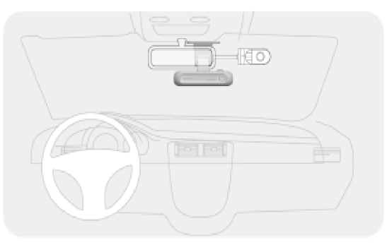
Select a suitable location for the mounting bracket. The recommended position is to install the camera lens at the vehicle centerline.
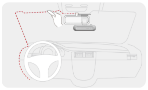
Install the dashcam behind the rear-view mirror where possible. Clean the windshield to make sure all dirt is removed.

Wiring can be run underneath the trim on the interior of the vehicle. If needed, a 12-volt installer can help you hide wiring for a professional look.
Mobile App
|
To verify camera view, calibrate an AI dashcam, or retrieve videos directly from the camera without using the cellular network, the Mobile App below can be used. |
This process is optional for those not using camera AI abilities but recommended to ensure you have a good view of the road
 QuCam+ from Google


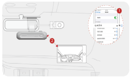
For best results, please turn on the ignition. Click the function button twice (Quick double tap) to activate the Wi-Fi hotspot after the dash camera is running. An audio response “enable wifi” will occur.
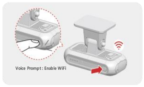
Locate the camera’s Wifi network from your phone’s list of Wifi services (named “queclink”). The default Password should be 12345678. If this password fails, please contact our support team.
If prompted that the network has no internet access, click “yes” to stay connected to this WiFi network. Missing this step may prevent your phone from connecting or staying connected to the camera hotspot.
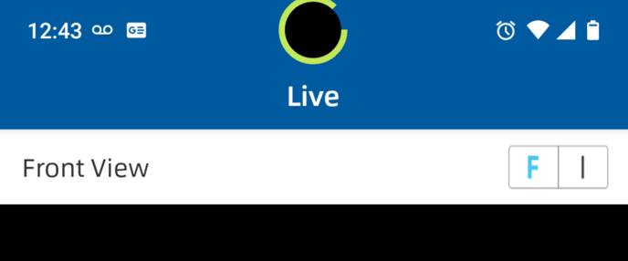
Using the Live tab in the QuCam software to view your Front facing camera.

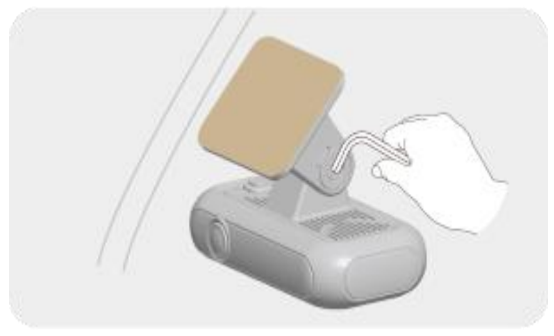
Unscrew the bracket shaft hex screw and adjust the camera’s angle so it has a straight and level view to the road ahead.
Remember to remove the Lens Cover and protective lens film.
When the angle is correct, secure the camera’s position again using the hex screw.
(Optional) Cabin Camera
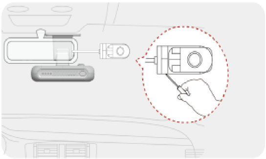
Select a location on the windshield that can view the entire cabin. Use the QuCam+ Application to check camera’s view if needed.

Plug the connector of the cabin camera into the Accessory Camera input.
Confirm the view of the camera is correct via the QuCam Mobile App.
Adjusting the angle of the cabin camera is possible with a Phillips screwdriver.
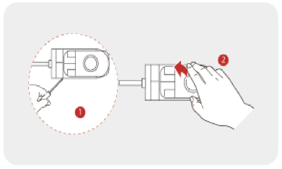
Remove the protective film on the lens, and use the screw to secure the camera’s new position.
(Optional) DMS Camera
This camera can only be installed attached to the dash.
Do not flip, rotate, or install on windshield or a-pillar.
The DMS is a driver-facing Infrared camera with optional AI that monitors for driver behaviour and safety events:
-
Phone Calling

-
Smoking
-
Distraction
-
Yawning
-
Eyes Closed
The camera should view the driver’s face easily, but not interfere significantly with the driver’s view of the road.
 The DMS camera can be installed on the dash with adhesive tape, or 4x screws.
The camera should be 50 - 90cm (20 - 35 inches) away from the driver’s face. If the camera is too close, some behaviours may not be detected correctly.
DMS AI calibration:
This process is only required for AI use
Your camera’s AI option must be activated to see the calibration interface. If you did not order your camera with AI ability turned on, you will not see the Calibration option.
From your camera’s Live menu, select Interior View by clicking on the “I” (Interior) above the image.

Ensure the driver’s head appears inside the calibration face frame.

(blue colour is only for this demonstration image)
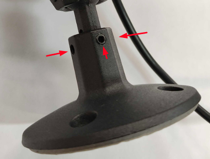
If the driver’s face is not within the frame, please adjust the DMS camera’s bracket with the included allen key. There are two points of adjustment:
 The rotation and pitch of the camera are adjusted by loosening the 3 screws just under the camera body itself.
The height can be adjusted by loosening 3 screws at the top
of the camera’s mounting plate.
When ready, Click “Start Calibration”

When complete, the status below the button will read “Calibration Completed”

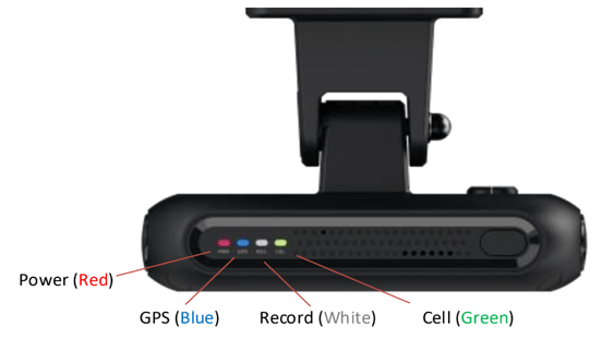
LED Lights
|
Status |
Power |
GPS |
Record |
Cell |
|
ON |
Power On or Sleep |
GPS Fix Normal |
Record Normal |
Network Connected |
|
OFF |
Power Off or Power Lost |
N/A |
Recording Stopped |
N/A |
|
Fast Blink |
Firmware Updating |
Searching for GPS fix |
Event Recording |
Searching for cell connection |
|
Slow Blink |
Low Power Voltage |
GPS Fix abnormal |
Record abnormal |
Network abnormal |
Video Download
Mobile App
While connected to the device via Wifi, Select “Camera” from the bottom menu of the application.

A list of available videos will appear on the screen. They can be downloaded to your device in MP4 format.
Tap the Select check button at the top:

Check boxes will appear next to each video, allowing you to download your selected choices.

PosiTrace Platform
Remote downloads of up to 1 minute in duration are available through the PosiTrace Platform (called Locate). For longer videos, please access the camera via the QuCam Mobile application or use the Computer download option.
There are a number of ways to download video via the PosiTrace Platform, such as clicking the
“Request Video” button on your vehicle’s Equipment pop-up, or on a trip point or event.
You can also reach the Video Request area by navigating through Account > Equipment List, viewing your vehicle, and clicking the Video tab > Video Requests > Add New.

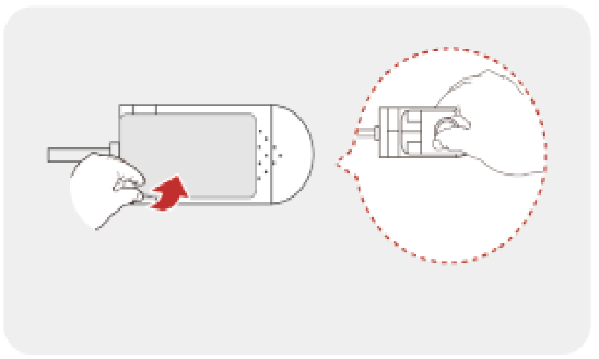
From a Computer
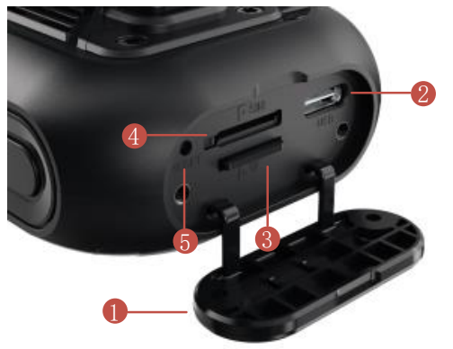
Video can be downloaded directly from the camera’s SD card. Use the included screwdriver to
open the side panel of the camera, and remove the SD card (#3 in picture). Pressing the card
should unlock it out for removal.
Do not remove the sim card (#4).
Insert SD card into a compatible card reader slot on your computer. If you do not have a card reader, USB reader options are available from most computer retailers or big box options like Amazon.
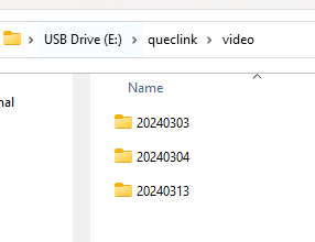
The files will be available in MP4 format in the following folder structure: USB drive > Queclink > Video > (Date folders)
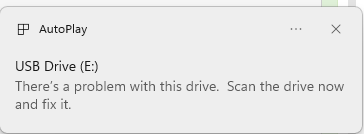
When removing your card from the camera and inserting it into a PC, you may notice a warning
about the card experiencing a problem. This is normal as there is no ability to software-eject the card from the camera before pulling it out.
Click the notification: You can choose to scan the card, but continuing without a scan should also be fine.